Warning
You are reading an old version of this documentation. If you want up-to-date information, please have a look at 2025.11 .Purging platforms
When a quick change of component is required, the purge option allows you to easily switch from making an “A” product to a “B” product and thus reduce changeover time while avoiding operator intervention during production. The purging principle is different for each Asycube :
The purge option for the Asycube 50 and 80 consists in :
(A) a platform with a special geometry, which allows the components to be evacuated.
(B) a box receiving purged components placed below the hopper. This box can be removed without tooling.
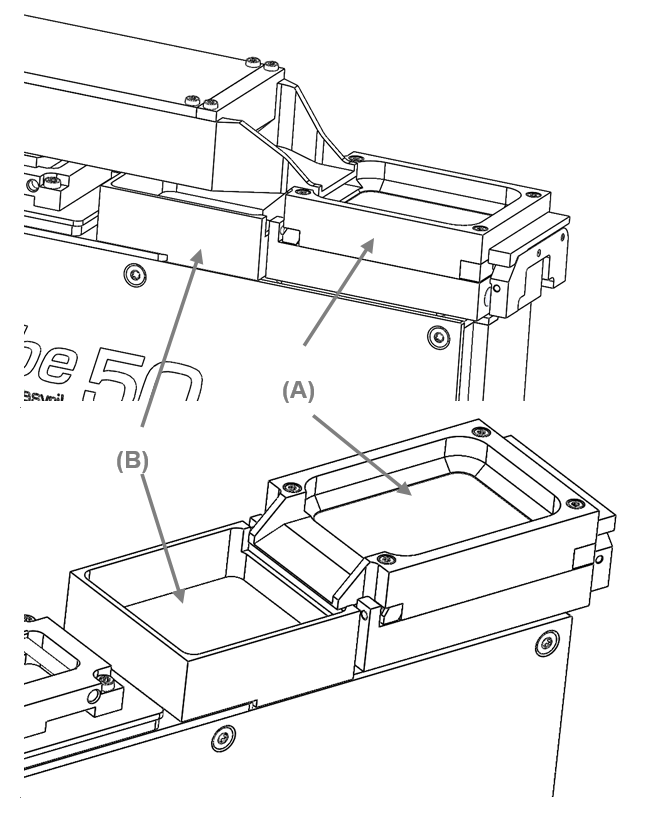
Fig. 83 Purge option
The purge option for the Asycube 240 consists in :
(A) A platform with a special geometry and an integrated flap to purge parts either to the left or the right.
(B) A purge actuator kit enabling the movement of the flap and its proper closure. It contains an electric actuator and a sensor.
(C) A purge part spout
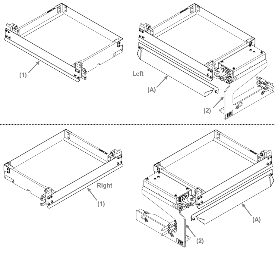
Note
The purge actuator kit is sold separately to the platform.
The purge spout is delivered with the purge actuator kit.
Cables are included with the purge actuator kit.
The side of the purge (right or left) can not be reconfigured after purchase.
The purge option for the Asycube 380 and 530 consists in :
(A) A purging frame with an integrated flap to purge parts either to the left or the right. It contains an electric actuator and a sensor to enable a proper closure of the flap.
(B) A purge part spout
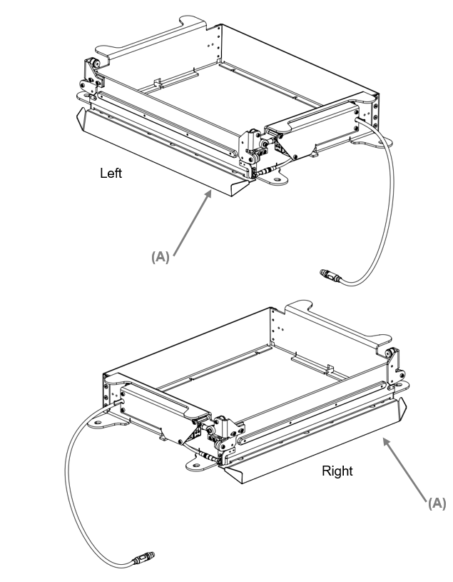
The flap is driven by an electric motor, and a sensor acknowledges its proper closure. The mechanism is controlled directly by the Asycube.
Note
The purge actuator kit is sold separately to the platform.
The purge spout is included with the purging frame.
Cables are included with the purge actuator kit.
Mechanical interfaces
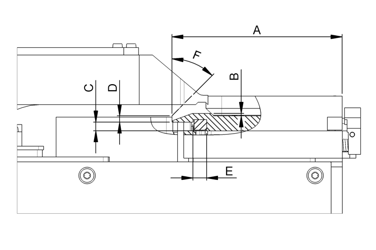
50 |
80 |
|
|---|---|---|
A |
68.7 mm |
90.7 mm |
B |
1 mm |
1 mm |
C |
3.5 mm |
3.5 mm |
D |
2.5 mm |
3.5 mm |
E |
5.5 mm |
5.5 mm |
F |
45° |
45° |
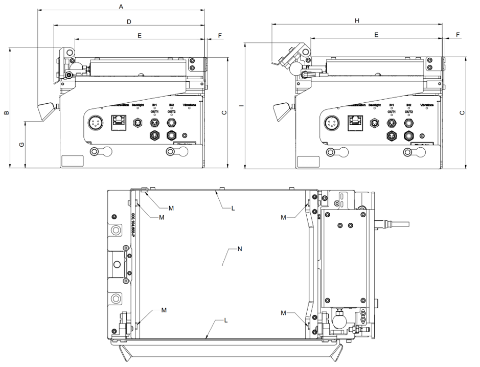
Asycube 240 |
|
|---|---|
A |
199 mm |
B±stroke |
144±2 mm |
C±stroke |
132±2 mm |
D |
180 mm |
E |
152 mm |
F |
4 mm |
G |
54 mm |
H |
201 mm |
I±stroke |
149±2 mm |
L |
Stainless steel 1.4301 |
M |
Stainless steel 1.4301 |
N |
POM (see product list) |
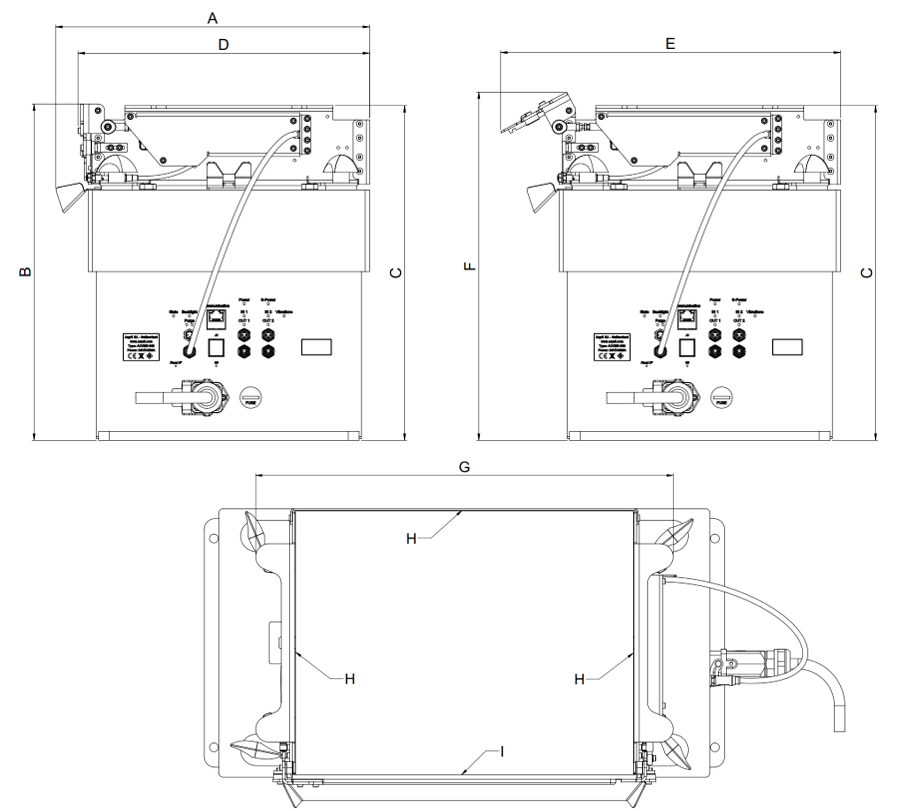
Asycube 380 |
Asycube 530 |
|||
|---|---|---|---|---|
Frame height |
H=60mm |
H=85mm |
H=68mm |
H=100mm |
A |
287 mm |
287 mm |
404 mm |
404 mm |
B ± stroke |
307±6 mm |
332±6 mm |
329±8 mm |
361±8 mm |
C ± stroke |
306±6 mm |
331±6 mm |
327±8 mm |
359±8 mm |
D |
264 mm |
264 mm |
381 mm |
381 mm |
E |
311 mm |
333 mm |
435 mm |
463 mm |
F |
316±6 mm |
341±6 mm |
338±8 mm |
370±8 mm |
G |
400 mm |
400 mm |
506 mm |
506 mm |
H |
Stainless steel 1.4301 |
|||
I |
POM-C (FDA) |
|||
Electrical interfaces
Not applicable for this type of Asycube.
Note
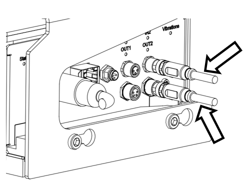
To use the purge actuator kit, plug the cable in the Asycube “IN2” / “OUT2” outputs. Remember to unplug the cable should you need to remove the system
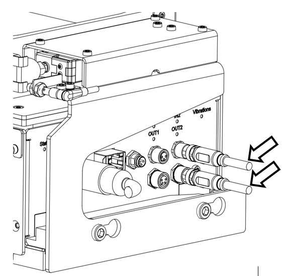
Note
When plugging in the purging frame, the motor will seek its origin position, hence emitting some noise. That noise may be heard while operating too, under certain circumstances.
Important
To prevent the motor from being prematurely damaged, all movements that don’t aim at emptying the platform must not be used.
(e.g. consider a purging system with the flap on the left. Only the “Left” vibration may be used. Similarly, wit a purging system whose flap is on the right, only the “Right” vibration may be used).
Note
To use the purge frame, plug the cable in the Asycube “Purge” output. Remember to unplug the cable should you need to remove the frame
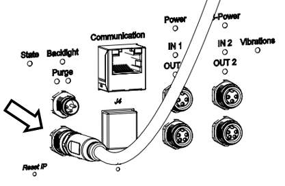
Note
When plugging in the purging frame, the motor will seek its origin position, hence emitting some noise. That noise may be heard while operating too, under certain circumstances.
Important
To prevent the motor from being prematurely damaged, all movements that don’t aim at emptying the platform must not be used.
(e.g. consider a purging system with the flap on the left. Only the “Left” vibration may be used. Similarly, with a purging system whose flap is on the right, only the “Right” vibration may be used).
Mounting purge kit
Not applicable for this type of Asycube.
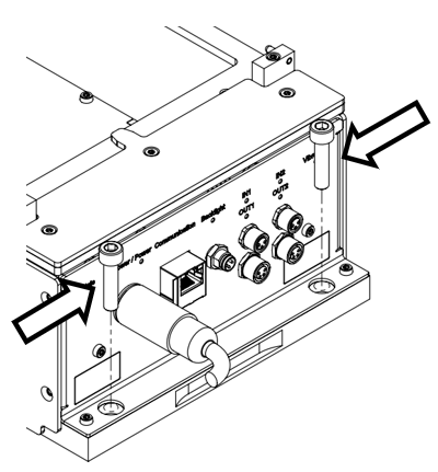
Step 1: Unscrew the Asycube on the connector side.
2 screws I5. 
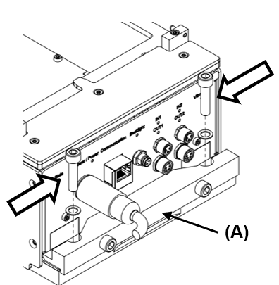
Step 2: Position the support (A). (take care to push it on the surface of the Asycube). Screw back the Asycube.
2 screws I5. 
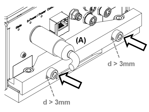
Step 3: Loosen the screws of the support to ensure a distance: d > 3mm, between the surface of the support (A) and the head of the screws.
2 screws I5. 
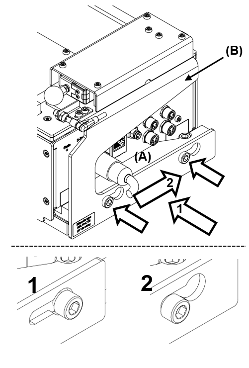
Step 4: Position the purge actuator kit (B) (1)-(2) and tighten the screws of the support (A).
2 screws I5 , 4.5Nm. 
Slide the purge actuator kit (B) in stall against the screws before tightening them. (Operation 2).
Step 5: Connect the purge actuator kit to the Asycube. Use the outputs: IN2 / OUT2.
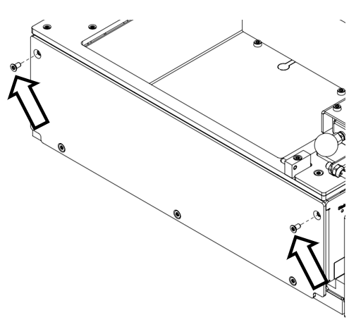
Step 6 (optionnal) : Remove 2 screws from the side plate.
2 screws Tx10. 
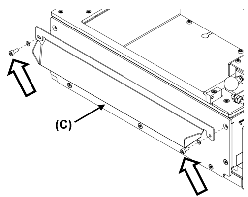
Step 7 (optionnal) : Screw the purge spout (C) on the base of the Asycube.
2 screws I2.5 - 1.2Nm. 
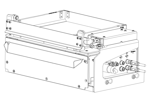
Step 8: Position the platform on the Asycube.
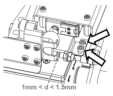
Step 9: Unscrew the sensor holder. Set the sensor at a distance between 1mm and 1.5mm from the sensor plate. Tighten the two screws of the sensor holder.
2 screws I2.5 - 1.2Nm. 
Step 10: Open Asycube Studio, select the “configuration” tab and enable the purge function.
Important
When the purge flap is open, do not use any other vibrations than left or right. If this constraint is not respected the mechanism could be irreparably damaged.
Important
The purge kit and the purge option activation modify the vibration behavior. Do not forget to deactivate the purge option when your remove the purge kit
Note
On the Asycube 240: When the purge option is enabled, the Input 2 and Output 2 are disabled and cannot be used to trigger a sequence or control a hopper.
Note
Default purge sequences (left and right) are stored in the sequence 2 and 3 of every Asycube 240, 380 and 530.
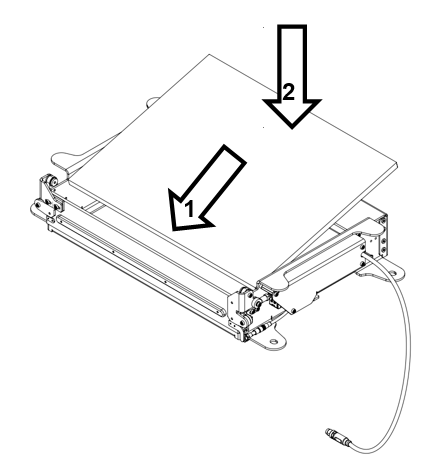
Step 1: Screw the platform in the purging frame.
8 screws Tx10 - 0.8Nm. 
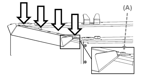
Step 2: Screw the purge spout on the base of the Asycube.
4 screws (A) Tx8 - 0.6Nm 
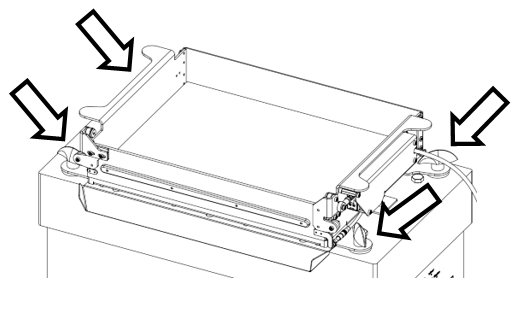
Step 3: Position the assembly on the Asycube. Screw the 4 handle screws.
Step 4: Position the purge actuator kit (B) (1)-(2) and tighten the screws of the support (A).
2 screws I5 , 4.5Nm. 