Warning
You are reading an old version of this documentation. If you want up-to-date information, please have a look at 2025.11 .Asycube actuators
Asycube 50/80
The Asycube 50 and 80 work with three actuators: Two in-plane actuators (Fig. 212: Act.1 and Act.2) and a vertical one (Fig. 212: Act.3). Below are some hints that are useful to adjust the vibrations:
Use a small vertical vibration (non-zero amplitude for Act.3) for smooth displacement of parts on the platform. Use a stronger vertical vibration (larger amplitude for Act.3) for the Flip vibration.
Except for the ‘Flip’ vibration, the frequency of all platform vibrations is usually identical, meaning that once a suitable frequency is found for the displacement of the parts on the platform, the same frequency can be used for other types of displacement.
The direction of the movement of the parts on the platform is a result of the combination of the two in-plane actuator vibrations (Act. 1 and Act.2). Switching the phase from 0° to 180° inverts the direction of displacement (Fig. 212). The amplitude of the Act. 3. may be different from one direction of movement to the other.
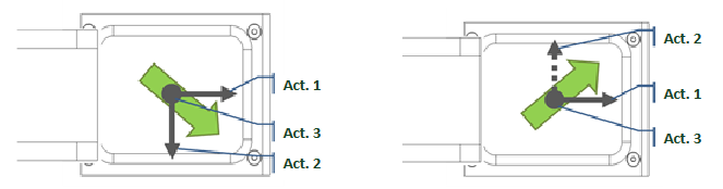
Fig. 212 Asycube 50 and 80 – Actuator disposition and example (green arrow) (solid line: 0° phase, dashed line: 180° phase)
If the parts do not move exactly towards the desired target, one can adjust the amplitude of the two in-plane actuators (Act.1 and Act.2) in order to correct the displacement direction of the parts.
Note
The hints provided are general and may not be perfectly suited to your Asycube. We recommend the use of vibration set 26 as a starting point, as it is configured and tested on your product using a standard part.
Asycube 240/380/530
The Asycube 240, 380 and 530 are equipped with four actuators, one in each corner of the platform. Below are some hints that are useful to adjust the vibrations:
The direction of the movement of the parts on the platform is the result of the combination of the excitation of actuators on the opposite side of the target end position of parts
For all the platform vibrations except the ‘Flip’, ‘Cross’- and ‘Long axis centering’ the frequency is usually the same. Once a suitable frequency is found for the displacement of the parts on the platform, it generally suits the other displacements too.
If the parts do not move exactly towards the desired target, it is possible to adjust the amplitude of neighboring actuators in order to correct the displacement direction of the parts.
Activating both actuators Act.3 and Act.4 makes the parts move away from them, resulting in this case in a forward vibration. When choosing an amplitude that is larger for actuator Act.1 than for the two neighboring actuators Act.2 and Act.3, we obtain a diagonal movement of parts (backward left vibration).
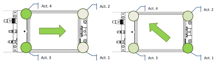
Fig. 213 Asycube 240, 380 and 530 – Actuator disposition and example (green: Activated, grey: Deactivated)
Note
The hints provided are general and may not be perfectly suited to your Asycube. We recommend the use of vibration set 26 as a starting point, as it is configured and tested on your product using a standard part.