Warning
You are reading an old version of this documentation. If you want up-to-date information, please have a look at 2025.11 .Add-on instructions description
AO_Execute_Sequence
Inputs and Outputs description
This Add-On instruction can be used to trigger the execution of a vibration sequence. This Add-On instruction also allows to turn ON or OFF the backlight of the Asycube. One instance of this instruction is used per Asycube.
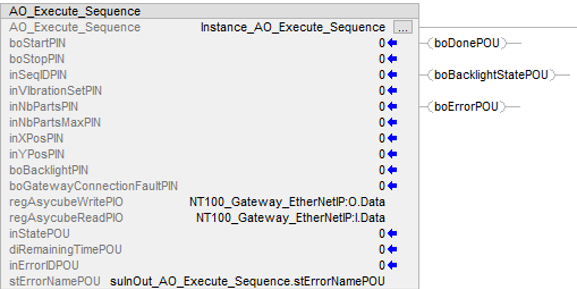
Fig. 188 AO_Execute_Sequence
Variable |
Type |
Description |
|---|---|---|
|
Boolean |
A rising edge starts the sequence. |
|
Boolean |
A rising edge stops the sequence. |
If the system is in |
||
|
Integer |
Vibration ID (0..25) |
|
Integer |
Vibration recipe ID (1..26) |
|
Integer |
Number of remaining parts currently on the Asycube. |
|
Integer |
Desired number of parts that you want on the Asycube. |
|
Integer |
X Coordinate of the center of mass of the remaining parts (-100..100). Corresponds to 100x the values described in the coordinate system for the center of mass. |
|
Integer |
Y Coordinate of the center of mass of the remaining parts (-100..100). Corresponds to 100x the values described in the coordinate system for the center of mass. |
|
Boolean |
Turns ON and OFF the backlight |
|
Boolean |
Connection fault status of the gateway. |
Variable |
Type |
Description |
|---|---|---|
|
Integer |
State : 0 = Idle, 1 = Running, 2 = Stopping, 10 = Error |
|
Boolean |
A rising edge indicates the end of the sequence |
|
Boolean |
State: |
|
Double Integer |
Remaining time of the sequence |
|
Boolean |
Goes to |
|
Integer |
Error ID (See Error List) |
|
String |
Error Description (See Error List) |
Variable |
Type |
Description |
|---|---|---|
|
Integer[0..33] |
This input must be linked to the GVL structure containing the write registers (See Plugin installation and configuration to import the structure) |
|
Integer[0..33] |
This input must be linked to the GVL structure containing the read registers (See Plugin installation and configuration to import the structure) |
Error List
N° |
ID |
Cause |
Resolution |
|---|---|---|---|
700 |
Transition error |
Input that was activated is not allowed in the current state. |
Only use command when you are in the correct state. |
701 |
Modbus error |
Refer to Main Modbus exception codes |
|
702 |
Internal Modbus error |
Refer to Holding Register: error codes |
|
703 |
Warning |
Refer to Asycube warnings and alarms |
|
704 |
Alarms |
Refer to Asycube warnings and alarms |
|
705 |
Gateway disconnected from PLC |
Communication problem on the Ethernet/IP segment |
Check the cable between gateway and PLC |
706 |
Asycube disconnected from gateway |
Communication problem on the Modbus TCP segment |
Check the cable between gateway and Asycube |
707 |
Time out |
Connection was lost with the Asycube |
Check the cables. Check that the Asycube is supplied. Check the Gateway state. |
708 |
Wrong parameter |
Wrong input parameter |
Correct the wrong input parameter. |
709 |
- |
N/A |
- |
AO_Execute_Platform_Vibration
This Add-On instruction is used to execute a single platform vibration. Standard vibration or centering vibration can be triggered using this instruction.
Inputs and Outputs description
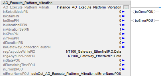
Fig. 189 AO_Execute_Platform_Vibration
Variable |
Type |
Description |
|---|---|---|
|
Integer |
Mode: 0 = Standard vibration, 1 = Centering vibration |
|
Boolean |
A rising edge starts the vibration. |
|
Boolean |
A rising edge stops the vibration. If the system is in |
|
Integer |
Vibration ID (0..25) |
|
Integer |
Vibration recipe ID (1..26) |
|
Integer |
X Coordinate of the center of mass of the remaining parts (-100..100). Corresponds to 100x the values described in the coordinate system for the center of mass. Only if Mode = 1. |
|
Integer |
Y Coordinate of the center of mass of the remaining parts (-100..100). Corresponds to 100x the values described in the coordinate system for the center of mass. Only if Mode = 1. |
|
Double Integer |
Duration of vibration (0 = unlimited). Only if Mode = 0. |
|
Boolean |
Connection fault status of the gateway |
Variable |
Type |
Description |
|---|---|---|
|
Integer |
State : 0 = Idle, 1 = Running, 2 = Stopping, 10 = Error |
|
Boolean |
A rising edge indicates the end of the sequence |
|
Double Integer |
Remaining time of the vibration. |
|
Boolean |
Goes to |
|
Integer |
Error ID (See Error List) |
|
String |
Error Description (See Error List) |
Variable |
Type |
Description |
|---|---|---|
|
Integer[0..33] |
This input must be linked to the GVL structure containing the write registers (See Plugin installation and configuration to import the structure) |
|
Integer[0..33] |
This input must be linked to the GVL structure containing the read registers (See Plugin installation and configuration to import the structure) |
Error List
N° |
ID |
Cause |
Resolution |
|---|---|---|---|
710 |
Transition error |
Input that was activated is not allowed in the current state. |
Only use command when you are in the correct state. |
711 |
Modbus error |
Refer to Main Modbus exception codes |
|
712 |
Internal Modbus error |
Refer to Holding Register: error codes |
|
713 |
Warning |
Refer to Asycube warnings and alarms |
|
714 |
Alarms |
Refer to Asycube warnings and alarms |
|
715 |
Gateway disconnected from PLC |
Communication problem on the Ethernet/IP segment |
Check the cable between gateway and PLC |
716 |
Asycube disconnected from gateway |
Communication problem on the Modbus TCP segment |
Check the cable between gateway and Asycube |
717 |
Time out |
Connection was lost with the Asycube |
Check the cables. Check that the Asycube is supplied. Check the Gateway state. |
718 |
Wrong parameter |
Wrong input parameter |
Correct the wrong input parameter. |
719 |
- |
N/A |
- |
AO_Execute_Hopper_Vibration
This function block is used to execute a single hopper vibration. Standard vibration or Quantity Adjusted vibration can be triggered using this block.
Inputs and Outputs description
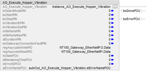
Fig. 190 AO_Execute_Hopper_Vibration
Variable |
Type |
Description |
|---|---|---|
|
Integer |
Mode: 0 = Standard vibration, 1 = Centering vibration |
|
Boolean |
A rising edge starts the vibration. |
|
Boolean |
A rising edge stops the vibration. If the system is in |
|
Integer |
Vibration ID (0..25) |
|
Integer |
Vibration recipe ID (1..26) |
|
Integer |
Number of remaining parts currently on the Asycube. Only if Mode = 1 |
|
Integer |
Desired number of parts that you want on the Asycube. Only if Mode = 1. |
|
Double Integer |
Duration of vibration (0 = unlimited). Only if Mode = 0. |
|
Boolean |
Connection fault status of the gateway |
Variable |
Type |
Description |
|---|---|---|
|
Integer |
State: 0 = IDLE, 1 = Running, 2 = Stopping, 10 = Error |
|
Boolean |
A rising edge indicates the end of the vibration. |
|
Double Integer |
Remaining time of the vibration. |
|
Boolean |
Goes to |
|
Integer |
Error ID (See Error List) |
|
String |
Error Description (See Error List) |
Variable |
Type |
Description |
|---|---|---|
|
Integer[0..33] |
This input must be linked to the GVL structure containing the write registers (See Plugin installation and configuration to import the structure) |
|
Integer[0..33] |
This input must be linked to the GVL structure containing the read registers (See Plugin installation and configuration to import the structure) |
Error List
N° |
ID |
Cause |
Resolution |
|---|---|---|---|
720 |
Transition error |
Input that was activated is not allowed in the current state. |
Only use command when you are in the correct state. |
721 |
Modbus error |
Refer to Main Modbus exception codes |
|
722 |
Internal Modbus error |
Refer to Holding Register: error codes |
|
723 |
Warning |
Refer to Asycube warnings and alarms |
|
724 |
Alarms |
Refer to Asycube warnings and alarms |
|
725 |
Gateway disconnected from PLC |
Communication problem on the Ethernet/IP segment |
Check the cable between gateway and PLC |
726 |
Asycube disconnected from gateway |
Communication problem on the Modbus TCP segment |
Check the cable between gateway and Asycube |
727 |
Time out |
Connection was lost with the Asycube |
Check the cables. Check that the Asycube is supplied. Check the Gateway state. |
728 |
Wrong parameter |
Wrong input parameter |
Correct the wrong input parameter. |
729 |
- |
N/A |
- |
FB_Backlight
This Add-On instruction is used to control the backlight. Backlight can be controlled in continuous or in flash mode.
Inputs and Outputs description
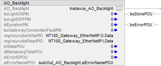
Fig. 191 AO_Backlight
Variable |
Type |
Description |
|---|---|---|
|
Boolean |
A rising edge turns ON the backlight |
|
Boolean |
A rising edge turns OFF the backlight If the system is in |
|
Double Integer |
Duration of the backlight. If 0, backlight turns OFF only if |
|
Boolean |
Connection fault status of the gateway. |
Variable |
Type |
Description |
|---|---|---|
|
Word |
State: 0 = IDLE, 1 = Running, 2 = Stopping, 10 = Error |
|
Double Integer |
Remaining time of backlight. If |
|
Boolean |
Goes to |
|
Integer |
Error ID (See Error List) |
|
String |
Error Description (See Error List) |
Variable |
Type |
Description |
|---|---|---|
|
Integer[0..33] |
This input must be linked to the GVL structure containing the write registers (See Plugin installation and configuration to import the structure) |
|
Integer[0..33] |
This input must be linked to the GVL structure containing the read registers (See Plugin installation and configuration to import the structure) |
Error List
N° |
ID |
Cause |
Resolution |
|---|---|---|---|
730 |
Transition error |
Input that was activated is not allowed in the current state. |
Only use command when you are in the correct state. |
731 |
Modbus error |
Refer to Main Modbus exception codes |
|
732 |
Internal Modbus error |
Refer to Holding Register: error codes |
|
733 |
Warning |
Refer to Asycube warnings and alarms |
|
734 |
Alarms |
Refer to Asycube warnings and alarms |
|
735 |
Gateway disconnected from PLC |
Communication problem on the Ethernet/IP segment |
Check the cable between gateway and PLC |
736 |
Asycube disconnected from gateway |
Communication problem on the Modbus TCP segment |
Check the cable between gateway and Asycube |
737 |
Time out |
Connection was lost with the Asycube |
Check the cables. Check that the Asycube is supplied. Check the Gateway state. |
739 |
- |
N/A |
- |