Warning
You are reading an old version of this documentation. If you want up-to-date information, please have a look at 2025.11 .2. Hopper Vibration
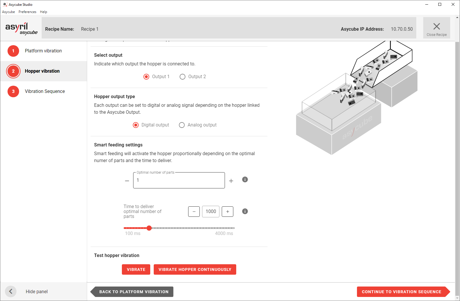
Fig. 95 Recipe Wizard - Hopper Vibration
The hopper vibration must be correctly configured to feed a regular amount of parts on the Asycube plate. You must find a good balance between:
A slow flow that takes too much time to fill the right amount of parts onto the Asycube.
A fast flow that risks overfill of the Asycube.
Adjust hopper/output parameters
Depending on the Asycube, a hopper is either integrated (Asycube 50 and 80) or not (Asycube 240, 380 and 530).
Asycube 50/80
The Asycube 50 and 80 have an integrated hopper to feed the necessary number of parts onto the platform in order to obtain at each cycle an acceptable number of parts available for picking by a robot.
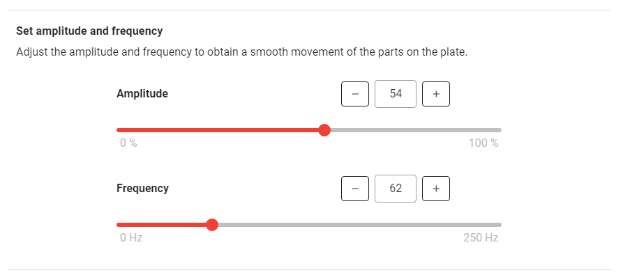
Fig. 96 Amplitude and Frequency tuning for Asycube 50/80
Amplitude: Amplitude of the signal sent to the actuator and defined as the percentage of the maximum amplitude
Increasing the amplitude makes the parts jump more.
Range: 0-100%
Frequency: The frequency of the signal sent to the actuator
Parts react more at a certain frequency depending on different factors (mass/geometry/rigidity).
Range: Typically 60-80Hz
Asycube 240/380/530
The Asycube 240, 380 and 530 are equipped with two outputs, generally used to control one or two hoppers to feed the necessary number of parts onto the platform in order to obtain at each cycle an acceptable number of parts available for picking by a robot.
The configuration of the outputs depends on what is actually connected to the outputs. For each recipe, you can choose which output is used and if that output is used in digital (Fig. 97) or analog (Fig. 98) mode.
Note
Refer to Digital outputs 1 and 2 to see how to connect to digital or analog outputs.
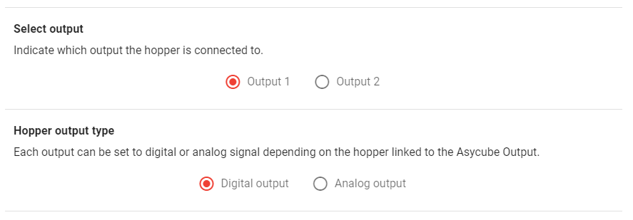
Fig. 97 Digital output configuration for Asycube 240/380/530
For analog mode, you can then choose the intensity in percentage: 100% corresponds to 10 V output.
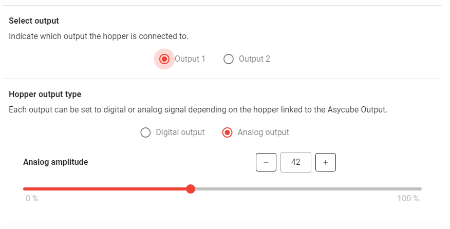
Fig. 98 Analog output configuration for Asycube 240/380/530
Important
When you have an Asycube 240 with a purging system, the second output on the Asycube will be needed to operate that system, meaning you will not be able to use it for a hopper.
Adjust Smart feeding settings
The following parameters will be used to parametrize the Smart Centering in the vibration sequence.
Set the optimal number of parts
To know what is the optimal number of parts, place some parts in the Asycube randomly distributed and stop adding parts when they start to be too close to each other. Count the parts on the Asycube, this is your optimal number of parts.
Input this number n in Asycube Studio. This number is necessary for smart feeding.
Important
The optimal number of parts parameter will be used as a reference when activating the hopper during production (see Smart Centering in the vibration sequence)
Set the duration of vibration
The number of parts delivered directly correlates to the duration and amplitude of the hopper vibrations. This must be set by trial and error.
First remove all the parts from the Asycube and fill the hopper with parts.
Important
The hopper must be filled as it would be in production.
Start the hopper vibration by clicking on .
Count the parts that fall onto the Asycube. If it is not the optimal number of parts, adapt the duration of vibration and repeat the steps until you get the right amount of parts on the Asycube.
Note
If the time to deliver the optimal number is too long, you may increase the hopper vibration amplitude to increase the speed at which the parts move in the hopper, and then adjust the duration again.