Warning
You are reading an old version of this documentation. If you want up-to-date information, please have a look at 2025.11 .Technical data tables
This chapter contains the technical parameters necessary to correctly install Asycube products.
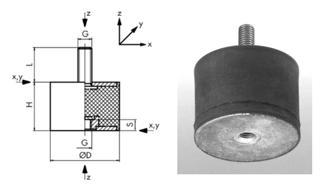
Acronyms
ØD |
diameter of the round buffer APSOvib |
G |
thread diameter |
H |
height of the round buffer APSOvib |
cz |
spring constant of the round buffer APSOvib; compression in Z direction (axial direction) |
Fz |
max. allowed compressive force of the round buffer APSOvib |
L |
thread length / male |
s |
thread depth / female |
Support characteristics
Note
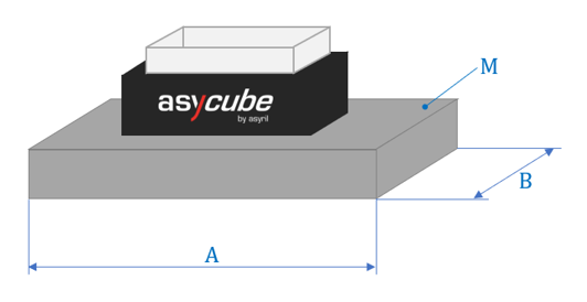
The thickness of the support must be calculated basing on requirements resumed in the table Make sure that the minimal mass [M] requirement is respected.
Asycube |
50 |
80 |
240 |
380 |
530 |
|---|---|---|---|---|---|
M [Kg] |
≥ 10 |
≥ 10 |
≥ 40 |
≥ 200 |
≥ 250 |
A [mm] |
≤ 600 |
≤ 600 |
≤ 600 |
≤ 1000 |
≤ 1200 |
B [mm] |
≤ 150 |
≤ 150 |
≤ 350 |
≤ 500 |
≤ 750 |

Screws detail
Asycube |
50 |
80 |
240 |
380 |
530 |
|---|---|---|---|---|---|
Qty. of screws |
2 |
4 |
4 |
4 |
4 |
Screw Ø |
M5 |
M5 |
M6 |
M8 |
M8 |
Vibration isolators details
Vibration isolator (Round / Rubber buffers) |
|||
|---|---|---|---|
Recommended for |
Asycube 240 |
Asycube 380 |
Asycube 530 |
APSO Ref. |
12.2034.0103 |
12.2034.0293 |
12.2034.0353 |
ØD [mm] |
16 |
40 |
50 |
H [mm] |
20 |
40 |
50 |
G [mm] |
M5 |
M8 |
M10 |
L [mm] |
12 |
25 |
25 |
s [mm] |
3 |
8 |
10 |
cz [N/mm] |
50 |
180 |
190 |
Fz [N] |
120 |
690 |
1000 |
Qty. [-] |
4 |
4 |
4 |
Vibration isolator (Round / Rubber buffers) |
|||
|---|---|---|---|
Recommended for |
Asycube 240 |
Asycube 380 |
Asycube 530 |
ELESA Ref. |
411771 DVA.2-15-20-M4-10-55 |
412021 DVA.2-50-45-M10-28-55 |
|
ØD [mm] |
15 |
50 |
|
H [mm] |
20 |
45 |
|
G [mm] |
M4 |
M10 |
|
L [mm] |
10 |
28 |
|
s [mm] |
4 |
10 |
|
cz [N/mm] |
47 |
182 |
|
Fz [N] |
234 |
2046 |
|
Qty. [-] |
4 |
4 |
|

Fig. 212 Vibration isolator (round buffer) details
Important
Make sure that total mass of Asycube, support and components will not exceed the max. allowed compressive force of the round buffers [Fz]. If this scenario occurs new round buffers must be selected.