Warning
You are reading an old version of this documentation. If you want up-to-date information, please have a look at 2025.11 .Hoppers for Asycube 240, 380 and 530
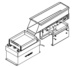
The hopper option sold by Asyril includes :
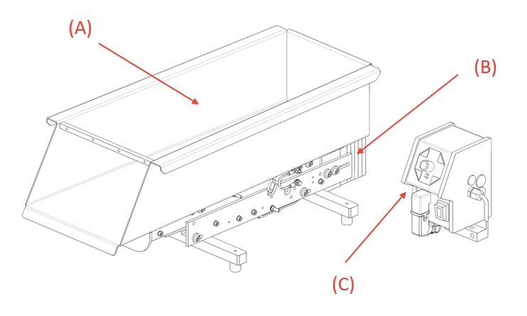
Fig. 56 Hoppers for Asycube 240, 380 and 530
The container (See Mechanical interfaces) (also called “tank”), receiving the parts : Depending on the size of the parts to be fed and the required machine autonomy, different sizes of hopper may be used (1L, 2L, 3L, 10L and 15L). These containers are in stainless steel Inox 1.4301.
The linear vibrator (See Mechanical interfaces) : this is the actuator of he hopper that enable the parts in the container to advance and drop onto the Asycube.
The Control Unit : used to adjust the hopper vibration amplitude
The set of cables (See Electrical interfaces): Three different cables are included in this set :
Incoming Power cable : links the hopper controller to the linear vibrator
Digital Control Cable : links the hopper controller to the Asycube
Power Cable : links the hopper controller to the power supply
Quick start instructions
Remove contents from box
Qty 1 – Hopper
Qty 1 – Hopper Control Unit
Qty 3 Cables: Incoming Power, Power Cable to Hopper, Digital Control Cable
Install and mount the Hopper see more details in Mounting
Mount the Hopper Control Unit. See more details in Mounting
Connect the Digital Control Cable from the Asycube Digital Output Port to the Hopper Control Unit.
Connect the Power Cable from the Hopper to the Hopper Control Unit.
Connect Incoming Power. Either 115V or 230V and 50Hz or 60Hz.
Important
The input voltage AND frequency must match the voltage and frequency of the Hopper Vibrating Mechanism. If this is not respected, the hopper could be irreparably damaged
Turn the Hopper Control Unit ON/OFF switch to ON.
Actuate the Digital Output of the Asycube.
Confirm that the Hopper is vibrating.
Adjust the vibration level as needed with the Potentiometer (0-100%) on the Hopper Control Unit.
Electrical interfaces
Wiring diagram
The hopper is supplied with the controller and cables ready to be installed. Depending on the model chosen, the hopper should be supplied with :
115V (+10%/-15%), 50Hz, 6A
115V (+10%/-15%), 60Hz, 6A
230V (+10%/-15%), 50Hz, 6A
230V (+10%/-15%), 60Hz, 6A
Important
The input voltage AND frequency must match the voltage and frequency of the Hopper Vibrating Mechanism. If this is not respected, the hopper could be irreparably damaged.
Number |
Signal |
Internal wires |
Hopper control unit cable |
|---|---|---|---|
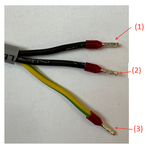
1 |
L |
Labeled 1 or brown |
|
2 |
N |
Labeled 2 or blue |
|
3 |
PE |
Ground (green/yellow) |
Control Unit
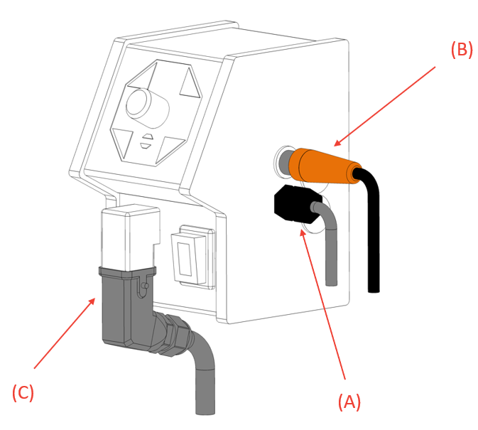
Fig. 57 Control unit
(A) Power Cable : links the hopper controller to the power supply.
(B) Digital Control Cable : links the hopper controller to the Asycube.
(C) Incoming Power cable : links the hopper controller to the linear vibrator.
The control unit is mounted on a mounting bracket (A) with the following dimensions.
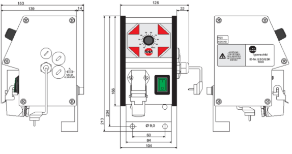
Fig. 58 Control unit
Note
Place the control unit in order to reach the potentiometer.
Mechanical interfaces
The different variants of hoppers (1L, 2L, 3L, 10L and 15L) can be mounted on the back or on the side of the Asycube. This enables applications such as “Dualfeeding” where two different parts are being fed onto the same Asycube simultaneously via two separated hoppers, as illustrated in Fig. 59
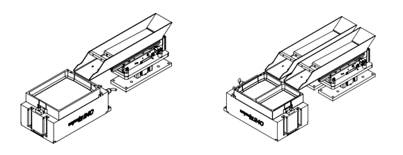
Fig. 59 Illustration of monofeeding versus dualfeeding
Note
With dualfeeding applications, since both parts will share the same vibration settings, attention must be paid to how parts are combined. A very heavy and large part combined with a light and small one might not give satisfying results. Since many factors can affect the vibration characteristics, we strongly advise you to perform some preliminary tests first.
The table below summarizes which hopper size can be used in conjunction with which Asycube with “mono” or “dual” feeding applications:
Asycube 240 |
Asycube 380 |
Asycube 530 |
|
|---|---|---|---|
1L Hopper |
mono / dualfeeding |
mono / dualfeeding |
mono / dualfeeding |
2L Hopper |
monofeeding |
mono / dualfeeding |
mono / dualfeeding |
3L Hopper |
monofeeding |
mono / dualfeeding |
mono / dualfeeding |
10L Hopper |
not compatible |
mono / dualfeeding* |
mono / dualfeeding* |
15L Hopper |
not compatible |
not compatible |
mono / dualfeeding* |
* Larger hoppers can only be placed on the Asycube’s small side for dualfeeding setups.
Note
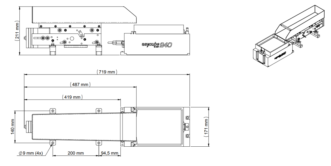
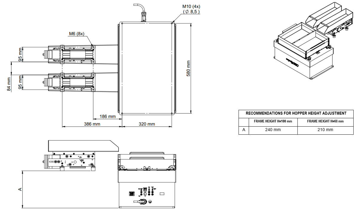
2L and 3L Hoppers are delivered with mounting feet which can be fastened to the machine base directly at the right height for an Asycube 240 using four M8x20 screws.
Note
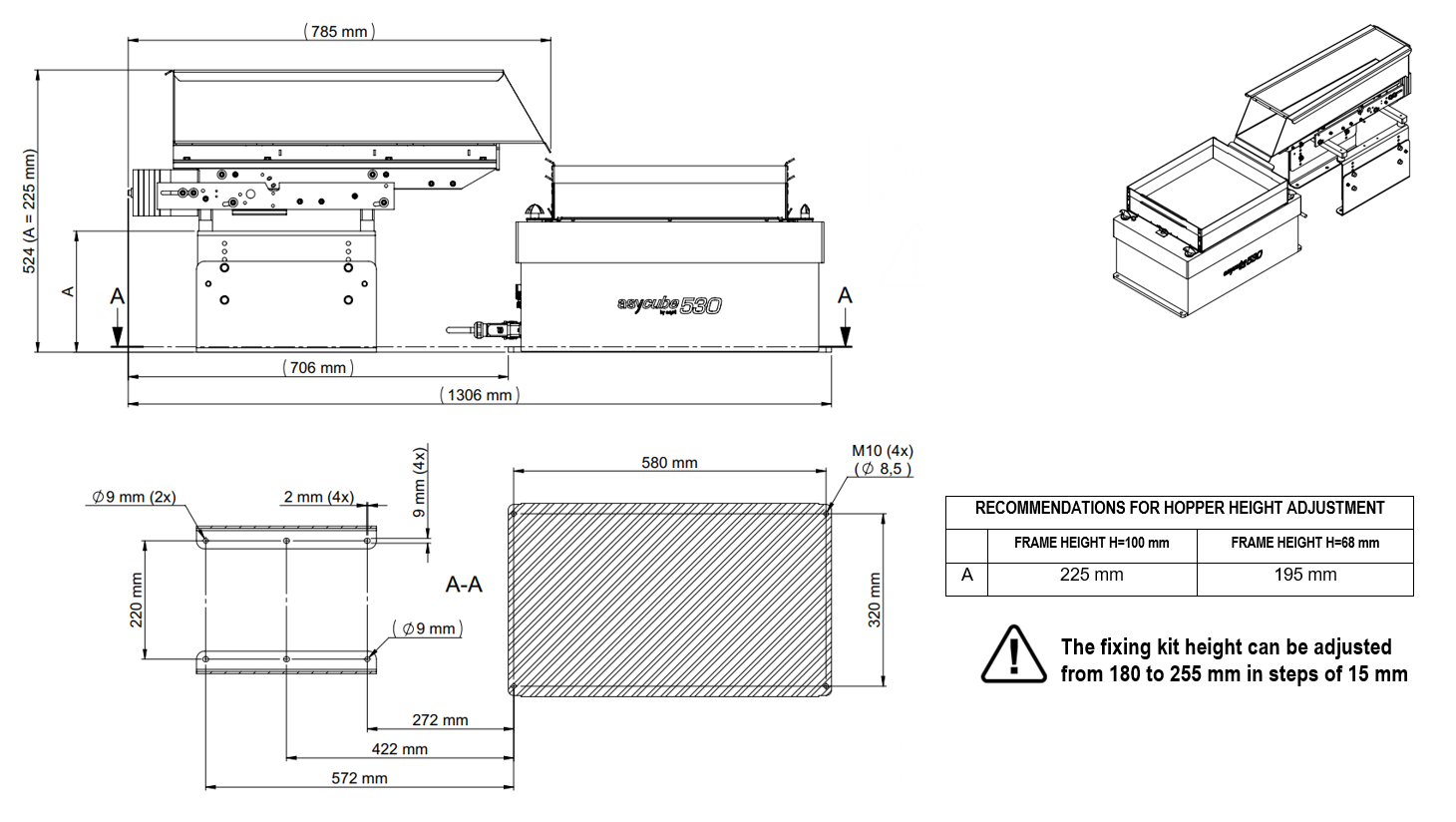
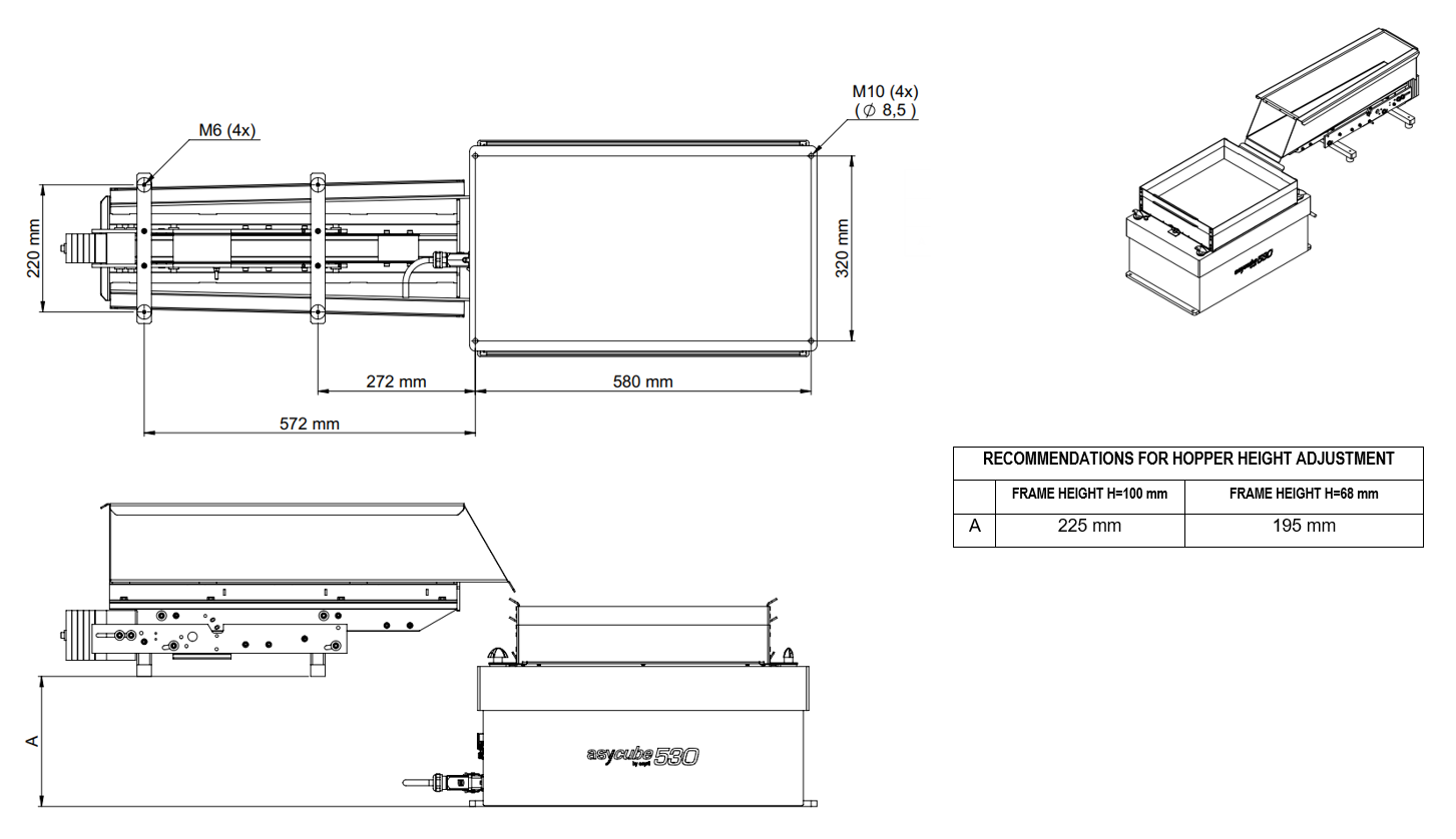
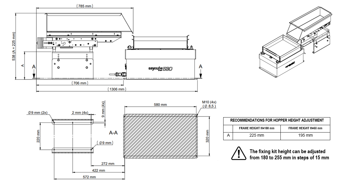
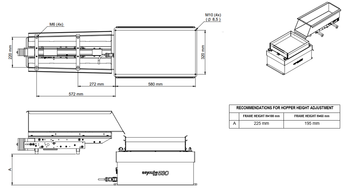
When pairing 1L, 2L, 3L, 10L and 15L hoppers with Asycube 380 and Asycube 530, the optional “MODULAR HOPPER FIXATION KIT” allows the hopper to be mounted at the ideal height.
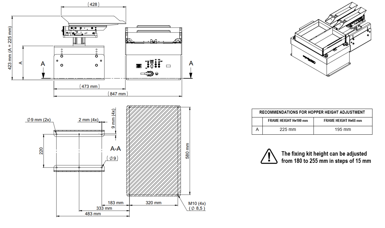
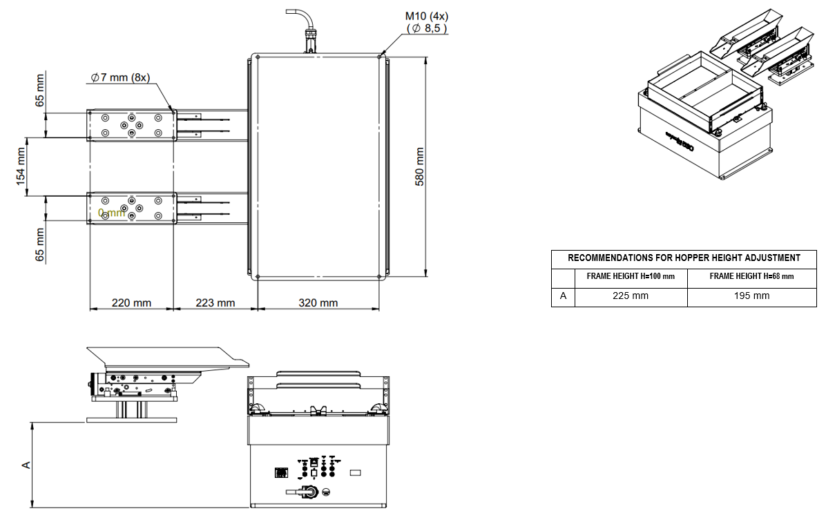
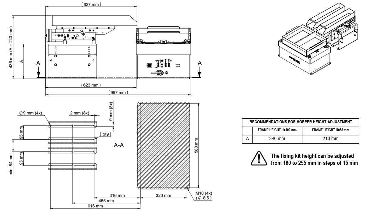
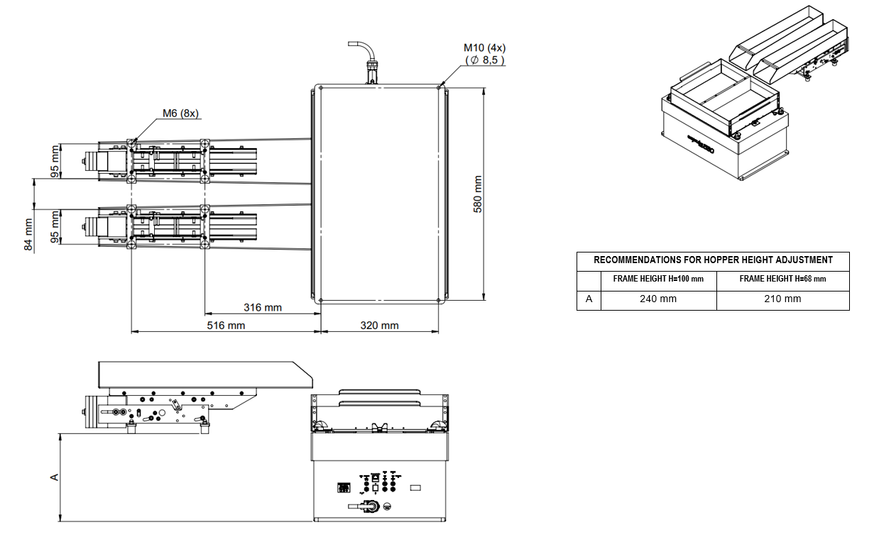
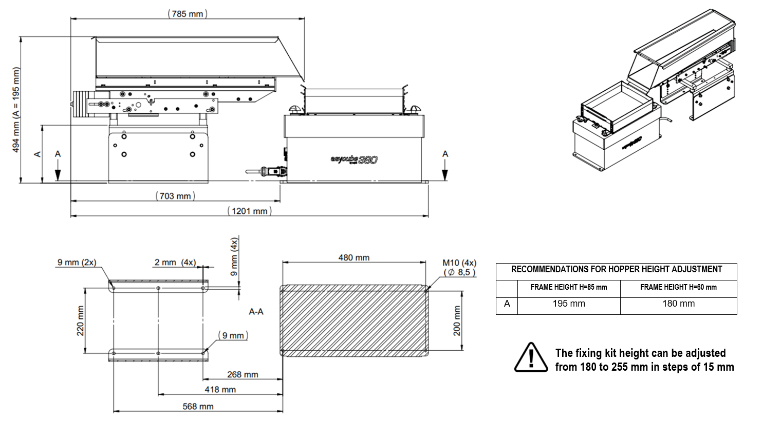
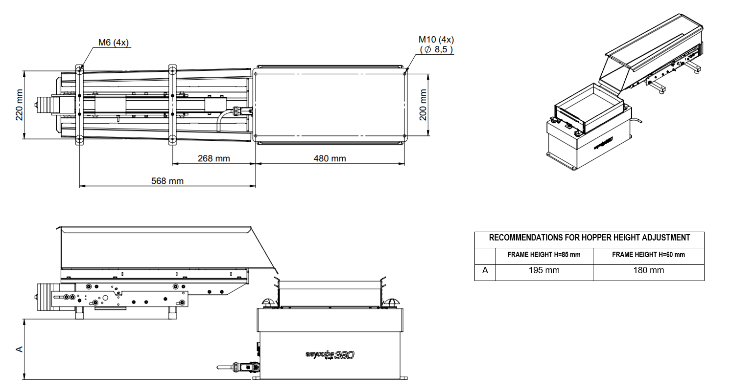
The following diagrams represent at which height the different hoppers shall be mounted and the position of the holes to fix the hopper to the machine base plate.
1 L hopper
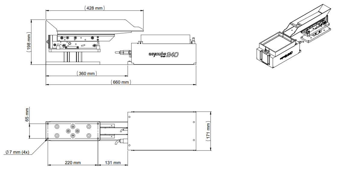
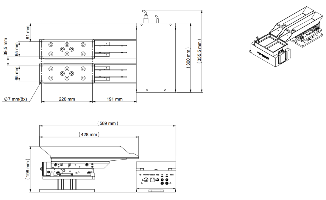
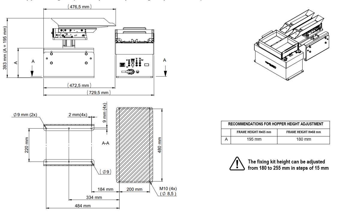
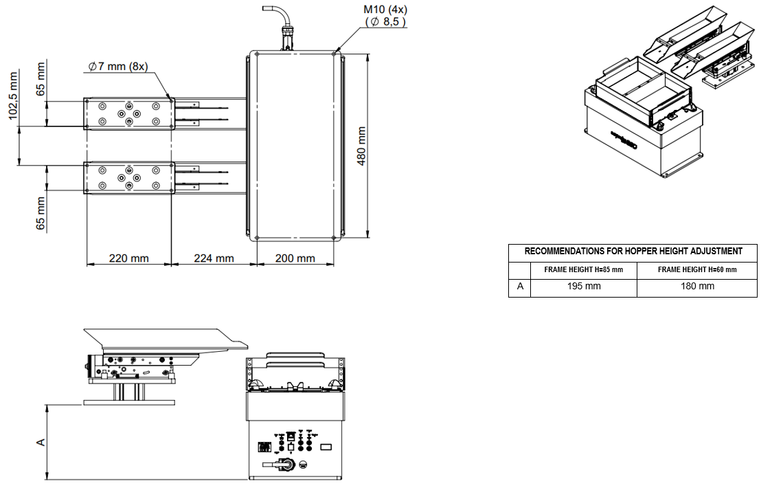
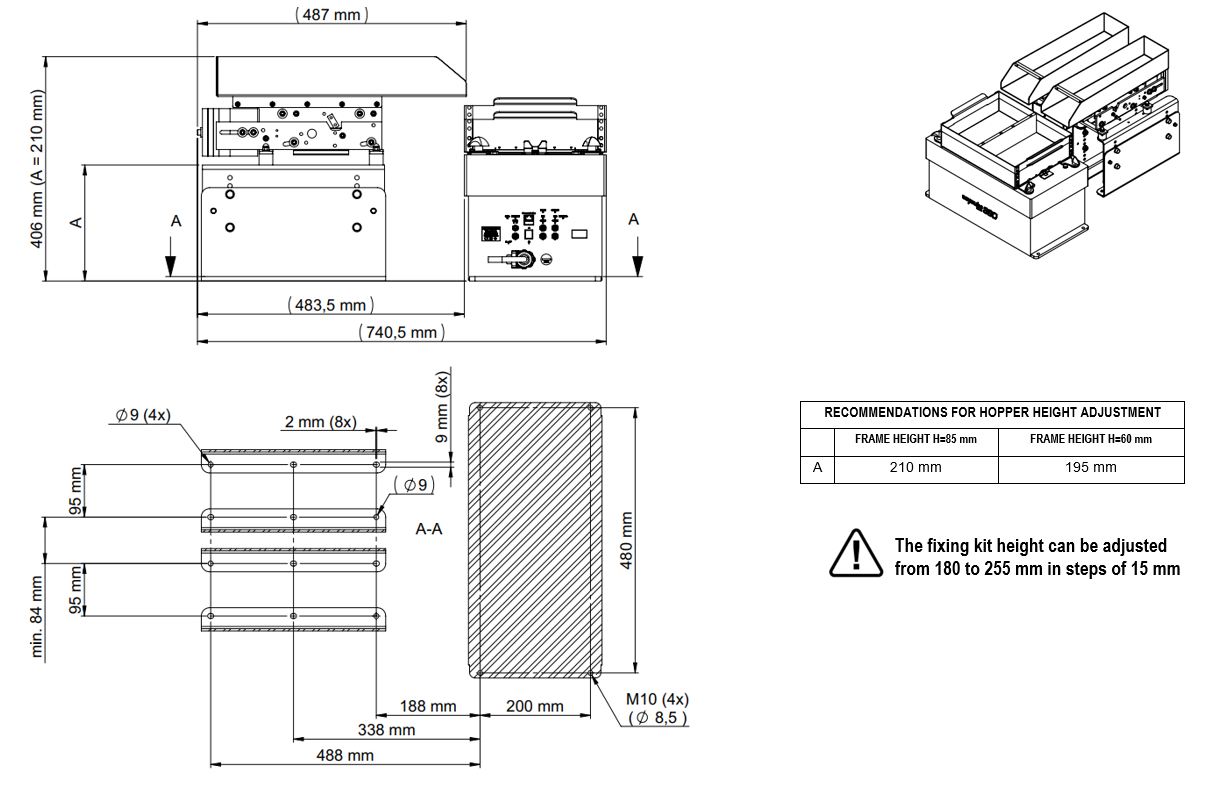
2 L hopper
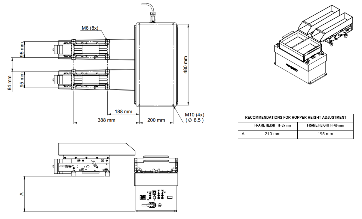
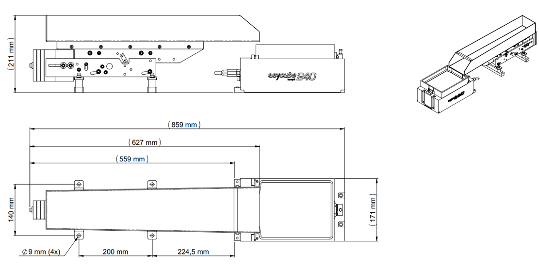
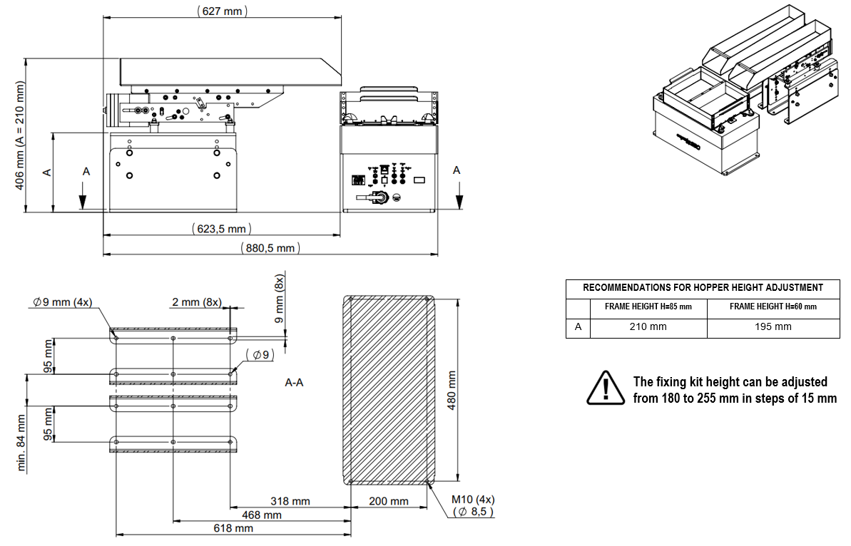
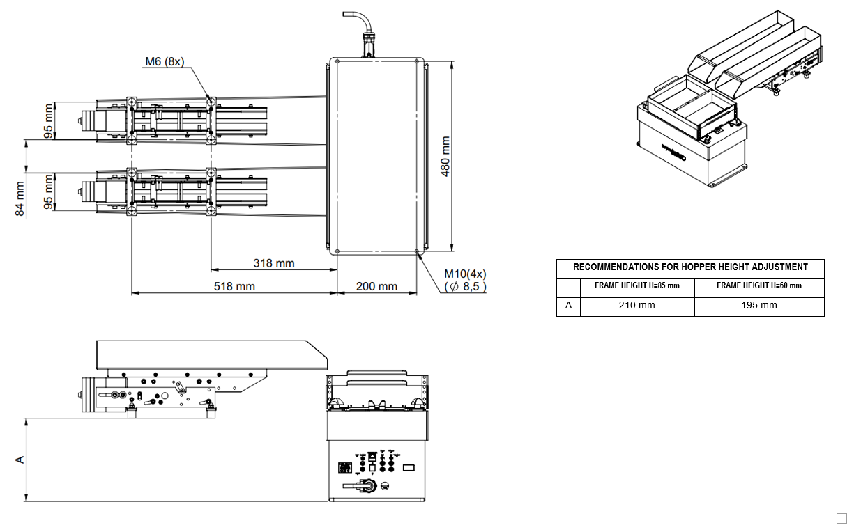
3 L hopper mechanical interfaces
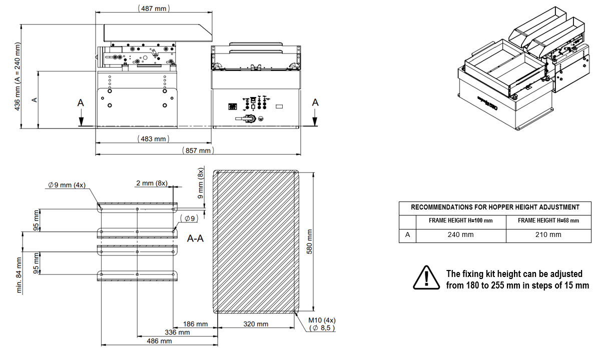
10 L hopper mechanical interfaces
15 L hopper mechanical interfaces
Modular fixing kit
Tip
This section only concerns only the Asycube 380/530.
The modular fixing kit allows to position the hopper at a height perfectly adapted to the Asycube 380/530. The assembly instructions are explained below:
Step 1
Choose the fixation height and fasten the first half with 2x M5 screws
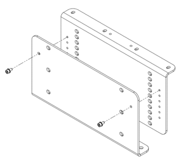
Note
The fixing kit height can be adjusted from 180 to 255 mm in steps of 15 mm
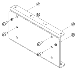
Step 2
Secure by fastening the 4x M8 screws with nuts
Step 3
Repeat Step 1 and 2 for the second half
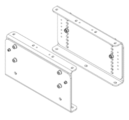
Step 4
Fasten the modular fixing kit on the machine base plate and then fix the hopper onto it