Warning
You are reading an old version of this documentation. If you want up-to-date information, please have a look at 2025.11 .Custom platform
A custom platform is necessary to orient the part correctly when the natural resting position of the parts does not match the picking orientation. Specific platforms can be designed to include grooves, holes, pockets, etc.
Note
Bespoke platforms are developed on demand by Asyril Support team. For more information, contact us.
While Standard plate are delivered with the Fixation kit (the frame for Asycube 380/530), must be ordered in addition to custom platforms.
Grooves
A structured platform with deep grooves is used to supply screw-type components to be fitted vertically. A platform with non-traversing grooves is used to supply components with a maximum length of 60 mm, see Fig. 55. For longer parts, grooves are manufactured through the whole thickness of the plate, see Fig. 56.
Fig. 54 Representation of a platform with grooves
The width of the groove(d’) is determined by the diameter of the component (d). In general, 0.05mm to 0.1mm is added to the maximum diameter size (allow for tolerance!). The tolerance on the width of the groove, which will depend on the machining and is not identical on all sizes of Asycube, must also be taken into consideration. A 0/+ tolerance is preferred.
The depth of the groove (L’) is usually not very important because the workpiece does not rest on the bottom. It must therefore be large enough to allow the part to tip and not touch the bottom. For the tolerance, a 0/+ tolerance is usually used.
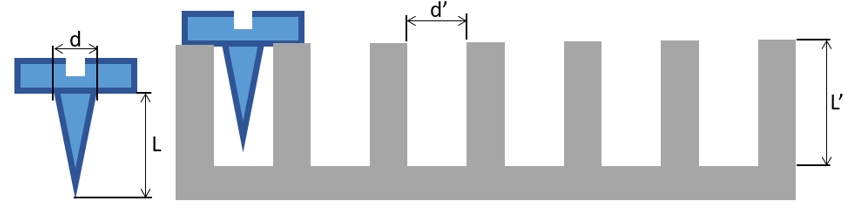
Fig. 55 non-traversing grooves can be manufactured for parts up the 60mm long.
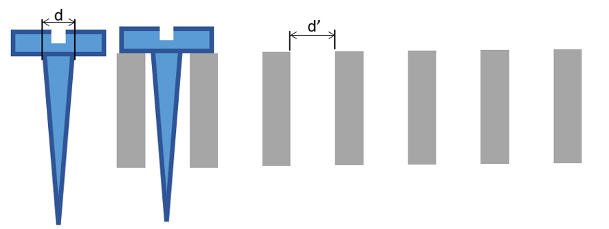
Fig. 56 For parts longer than 60mm, traversing grooves must be manufactured through the whole thickness of the plate.
d’ |
L’ |
|
|---|---|---|
Asycube 50 |
d + 0.05mm |
L’ > L |
Asycube 80 |
d + 0.05mm |
L’ > L |
Asycube 240 |
d + 0.1mm |
L’ > L |
Asycube 380 |
d + 0.5mm |
- |
Asycube 530 |
d + 1.0mm |
- |
Holes
Holes are useful when cylindrical components are to be fed and presented upright.
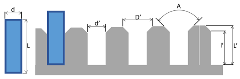
Fig. 57 Representation of a platform with holes
The diameter of the hole (d’) is the most important dimension of the plate. It is mandatory to have a large enough diameter to allow the part to straighten out once inside the hole. For parts up to 3.5mm of diameter, 0.05 mm is added to the maximum part diameter (d). However, for larger parts, with diameter larger than 3.5mm, as well as non-cylindrical parts (e.g. conical), a larger diameter is required.
The hole should be deep enough (l’) to allow the part to be guided along the walls if necessary. If the workpiece rests on the bottom, there is no need for a long guide.
It is preferable to guide the part at least on 1/3 of the height of the part (L), ideally ½, so that the piece stays as straight as possible.
Attention should also be paid to the residual height of the part above the plate (L’).
The chamfer (A) is essential to allow the part to fall into the hole. In most cases, the chamfer angle is 60°.
D’ |
d’ |
l’ |
A |
|
|---|---|---|---|---|
Asycube 50 |
> 0.5*L |
d + 0.05mm |
0.5*L |
60 |
Asycube 80 |
> 0.5*L |
d + 0.05mm |
0.5*L |
60 |
Asycube 240 |
> 0.5*L |
d + 0.1mm |
0.5*L |
60 |
Asycube 380 |
> 0.5*L |
d + 0.5mm |
0.5*L |
60 |
Asycube 530 |
> 0.5*L |
d + 1.0mm |
0.5*L |
60 |