Warning
You are reading an old version of this documentation. If you want up-to-date information, please have a look at 2025.11 .Power connection
Important
Before supplying power to the Asycube, check that your distribution voltage is the same as the nominal voltage (24 VDC).
Use PELV (protected extra-low voltage) nominal voltage.
Incorrect wiring of 0V and 24V can cause irreparable damages and void the warranty.
Strictly follow the power supply recommendations described in this section for your Asycube type.
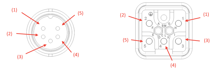
Fig. 21 Power connector Asycube 50/80/240 (left); Asycube 380/530 (right)
Pin |
Signal description |
Cable (Option) |
|---|---|---|
(1) |
24VDC PELV S-Power |
1 |
(2) |
0V GND S-Power |
2 |
(3) |
24VDC Power |
3 |
(4) |
0V GND Power |
4 |
(5) |
EARTH |
PE |
50/80/240 |
380/530 |
|
|---|---|---|
Connector type (on Asycube side) |
M16, 5 Poles, male |
Harting 09 12 005 3004 |
Characteristics |
Asycube 50/80 |
Asycube 240 |
Asycube 380 |
Asycube 530 |
|---|---|---|---|---|
Voltage |
24 VDC +5% |
24 VDC +5% |
24 VDC +5% |
24 VDC +5% |
Current consumption on Power |
5 A |
5 A |
4 A [1] |
6 A [1] |
Current consumption on S-Power |
1 A |
3 A |
16 A [1] |
14 A [1] |
Total Current Consumption |
6 A |
8 A |
20 A |
20 A |
Note
Both Power and S-Power can be connected to a single power supply or to two different power supplies. Select your power supplies with a nominal current rating as recommended in Table 5 with a current reserve of 150% for 3 seconds. The 0 V-GND and Earth signals of the two supplies are connected inside the Asycube.
Note
S-Power is the safety power for the backlight. Cutting S-Power ensures that the backlight stays OFF.
The following connection schematic shows the way to connect the Asycube depending if your application requires using an external relay to ensure that the backlight is safely switched off or not. In any case, both Power and S-Power have to be supplied for using the backlight.
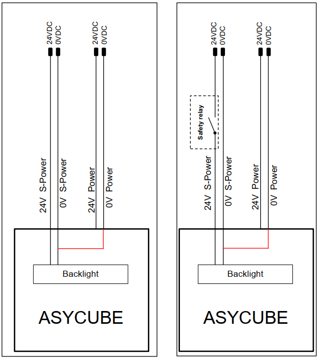
Fig. 22 Power connection without and with safety relay
Note
Both Power and S-Power can be connected to a single power supply or to two different power supplies. Select your power supplies with a nominal current rating as recommended in Table 5 with a current reserve of 150% for 3 seconds. The 0 V-GND and Earth signals of the two supplies are connected inside the Asycube.
Note
S-Power is the safety power for the backlight. Cutting S-Power ensures that the backlight stays OFF.
The following connection schematic shows the way to connect the Asycube depending if your application requires using an external relay to ensure that the backlight is safely switched off or not. In any case, both Power and S-Power have to be supplied for using the backlight.
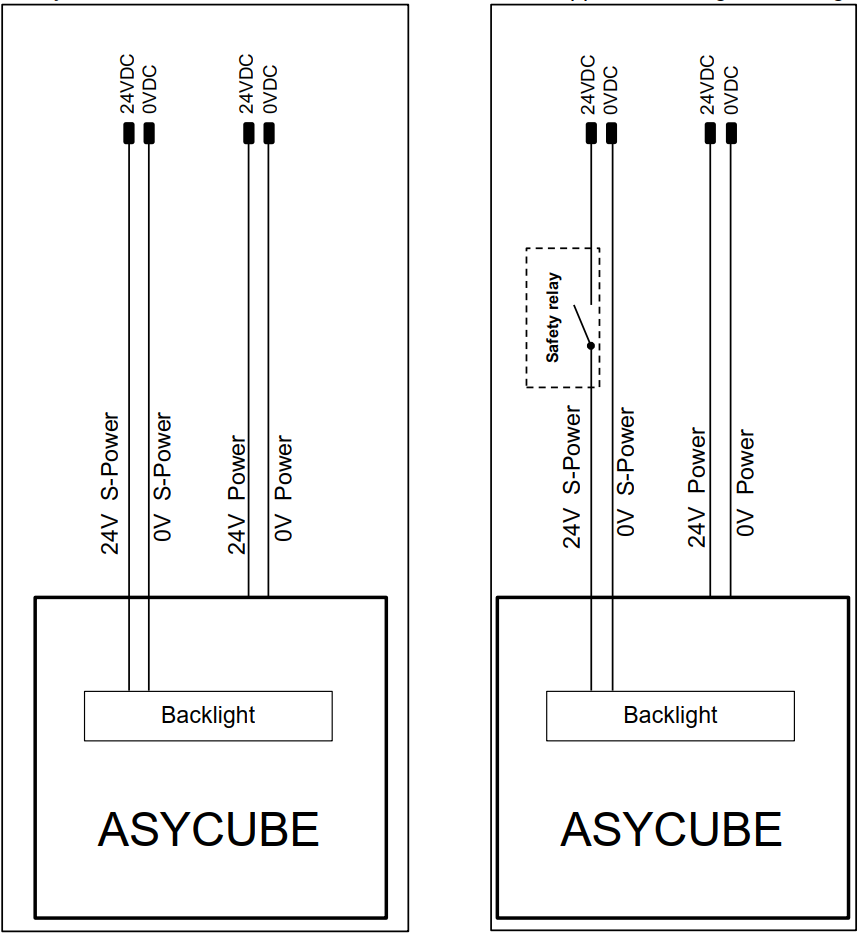
Fig. 23 Power connection without and with safety relay
Important
Both Power and S-Power must be connected to two different power supplies. Select your power supplies with a nominal current rating as recommended in Table 5 with a current reserve of 150% for 3 seconds. For the S-Power, the following three power supplies have been approved by Asyril:
PULS QS20.241
SIEMENS 6EP1336-3BA10
OMRON S8VK-S48024 24VDC/20A(480W)
The 0 V-GND and Earth signals of the two supplies are connected inside the Asycube.
Note
S-Power is the safety power for the backlight and actuators. Cutting this S-Power ensures that the backlight and actuators stay OFF.
Switching off this safety power deactivates the digital hopper outputs and the digital purge output. In any case, both Power and S-Power have to be supplied for using the backlight.
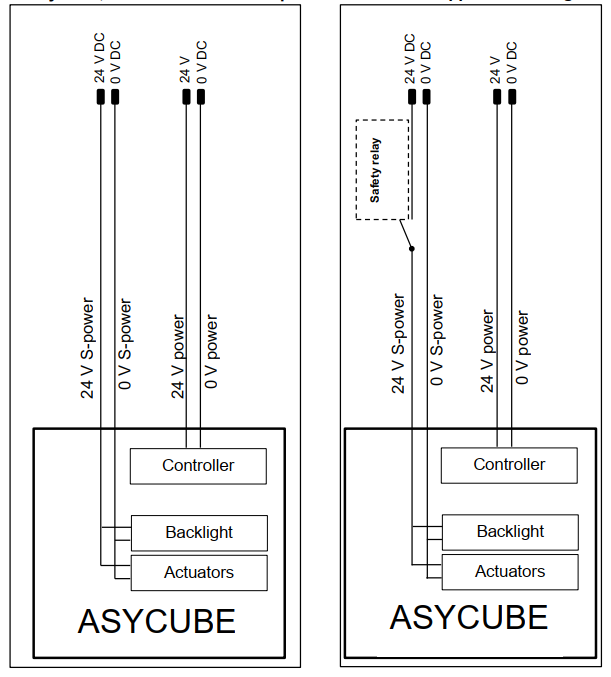
Fig. 24 Power connection without and with safety relay